Oct 10, 2026CNC Machining Tips
Designing CNC Machined Enclosures: Walls, Sealing, Threads and Finish
Design decisions for CNC machined enclosures — wall thickness, sealing, threading and finish choices that affect strength, cost and delivery.
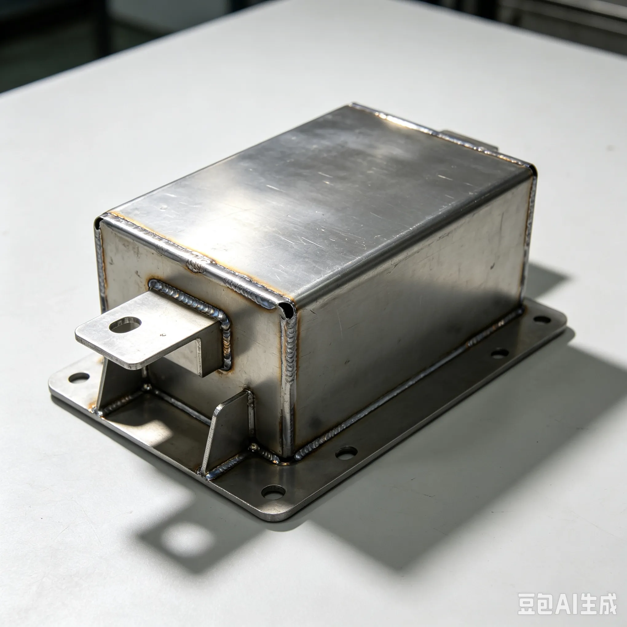
A CNC machined enclosure succeeds or fails on five design decisions: how thick the walls are, how the joint seals, how the threads carry load, how much room the internals get, and which finish goes where. If you are a design or process engineer at a hardware startup or equipment maker, detailing a machined housing around its electronics or mechanics, those five decisions shape both how it performs in service and how it machines.
This guide walks through each decision with its mechanism and the move you can make at the CAD stage. It is not written to choose between machining and sheet metal for your housing, and not written to supply sealing specifications. Cost and difficulty claims stay inferential until a supplier quotes your actual drawing; nothing here commits you to a purchase.
The decision you are actually stuck on
1. You are the design or process engineer who owns the enclosure drawing, so every structural decision lands on you first.
2. The housing has just been modeled around its internals and needs to be detailed for manufacture.
3. The structural decisions — thickness, sealing, threads, cavity, finish — are still open, and nothing tells you which will drive machining difficulty.
4. Decisions left to the quotation may come back as DFM comments, forcing a redesign loop and a second quote.
5. The build schedule may slip while the housing is reworked, and late changes can raise cost and scrap risk.
6. Work through the five decisions below and settle what you can before the drawing goes out.
When a machined housing is the right call
Machining from solid stock is usually the fit when the enclosure needs strength thin formed walls cannot provide, flat sealing faces, precise features for connectors or optics, or prototype and low-batch volumes. The counter-case: sheet metal usually costs less for larger, thinner-walled housings at higher volumes — a comparison this guide does not take on.
The five decisions that shape a machined enclosure
Wall thickness: stiffness, weight and machinability
A wall earns its thickness from stiffness and from the cutting process, not from a universal minimum number. Loads, spans and sealing-face flatness push thickness up; weight and material use push it down. Machining adds its own constraint: a thin wall has little stiffness to resist cutting forces, so it may flex, vibrate or distort as material comes off and stresses rebalance. Walls that vary widely in section can also move unevenly after machining, threatening sealing-face flatness. Where weight matters, ribs usually beat a uniformly thick wall.
Sealing: joint faces, grooves and mounting bosses
A machined enclosure seals at its joint, so the faces that meet the seal deserve functional callouts. Flatness is what lets a compressed gasket do its job; a wavy joint face leaks regardless of the seal you buy. Machining both mating faces in one setup keeps their relationship tight; every extra setup adds drift risk. A seal groove locates the seal and controls its compression, so the groove geometry has to match the seal section — a design-stage choice, not a post-machining fix. Raised bosses around ports and fasteners localize clamp load and shrink the area that has to stay flat. ProLathe machines to ±0.05 mm as a standard working tolerance, so the faces your seal depends on sit inside a defined, quotable band.
Threads and fastening in aluminum walls
Most machined housings close with screws into tapped holes, and in aluminum the thread is usually the weaker link: it carries less load than steel and can strip under repeated assembly or over-torque. Three habits reduce that risk. Give threads enough engagement for the load; commonly used rules of thumb are a starting point, not a guarantee. Plan inserts for repeated assembly or elevated loads — threaded inserts are a standard design consideration in aluminum housings, their locations belong on the drawing, and who fits them is a point to confirm, not assume. In blind holes, leave bottom clearance for the tap and the chips: a thread that bottoms out risks tap breakage and an incomplete thread.
Internal cavity and component clearance
The cavity exists to hold something, so model it: the board, the connectors, the cable routing. Clearance and mounting decisions belong here, because they decide the bosses, pockets and threads inside. Keep one point in view as the cavity deepens: a deep cavity forces longer tool reach, which can add time and cost — see how enclosure features drive machining cost before you commit to the depth.
Surface finish for the housing
Finish on an enclosure protects the material and sets the cosmetic tone. For aluminum housings, anodizing is the workhorse — corrosion and wear resistance, with dyes when a color is needed; sandblasting before it gives a uniform matte texture; painting covers color schemes anodizing cannot reach. Passivation suits stainless hardware; QPQ serves steel parts needing wear and corrosion performance. The confirmed in-house list is anodizing, QPQ, sandblasting, passivation and painting. Powder coating is common across the enclosure industry, but it is not on that confirmed in-house list, so it is an option to confirm with your supplier rather than a given. Call the finish and the appearance-critical faces out on the drawing — masking is easier to plan now than to fix later.
The enclosure design checklist
Fill each field with your housing's answers; an empty field is a decision still open:
wall thickness → stiffening route (section or ribs): ______ → uniform across sealing faces: yes / no
sealing path → seal type and groove-or-flat-joint decided: yes / no → flatness called out as functional: yes / no
fastening → thread sizes and engagement planned: ______ → insert locations marked: yes / no → blind-hole bottom clearance left: yes / no
internals → components modeled with clearance: ______
cavity depth → deep cavity flagged for the quote: yes / no
finish → finish type and priority faces selected: ______
decisions still open before the drawing goes out: ______
What this checklist cannot tell you
Groove geometry, insert selection and wall sections stay provisional until a supplier reviews the actual drawing. The checklist cannot measure your loads, validate a seal choice or price the part; process differences shop to shop mean the quotation prices the remaining risk. ProLathe's confirmed practice is a DFM-first review of every drawing before quoting.
For reference, ProLathe's confirmed capabilities:
CNC machining to ±0.05 mm standard working tolerance
Materials including aluminum 6061/7075, stainless 303/304/316/17-4, brass, bronze, steel, nylon and POM
In-house surface finishing: anodizing, QPQ, sandblasting, passivation, painting
Quotations within 24 hours
ISO 9001 certified
Run the checklist on your own housing
Run the enclosure checklist on your own design and mark which decisions are still open before the drawing goes out.
Two follow-ups depending on where your check lands:
Recording which decisions are settled and which are open is the whole action this page asks of you.