Oct 10, 2026CNC Machining Tips
CNC Parts for Robotics: Material, Tolerance and Finish Decisions That Matter
Material, tolerance and finish decisions for CNC robot parts — end effectors, structural links and housings, with selection guidance per component.
Robot CNC parts rarely fail for exotic reasons: a bearing seat out of fit, a wear pad chewed down against a rail, a mount corroded where coolant collects. If you are the design or process engineer who specs machined parts for a robotics startup or equipment maker, the decisions that keep those parts alive are material, tolerance and finish — made per component class, not per project.
This guide sorts those decisions by the three classes most robot builds share — structural links, end effectors and tooling, housings and motor mounts — and closes with a per-part checklist. It is not a build guide for actuators, motor selection or control electronics, and not a substitute for the alloy comparisons it links to. Loads and service life stay unverified until your assembly is tested; nothing here commits you to a purchase.
The decision you are actually stuck on
1. You are the design or process engineer who owns the drawings for a robot's machined parts.
2. A new build or revision is about to send links, end-effector components and housings out for quotation.
3. The assembly model shows what each part does, but nothing tells you which alloy, tolerance band and finish each class needs.
4. A wrong call may surface only at assembly or first test, forcing a re-quote and a second machining run.
5. The schedule may slip while replacements are machined, and the iteration budget burns on parts that should have been specified once.
6. Sort the parts into the three classes below, make the calls per class, and record them on the checklist before requesting quotes.
Start from the part class
Three classes cover most of what a robot sends out for machining.
Structural links and joints
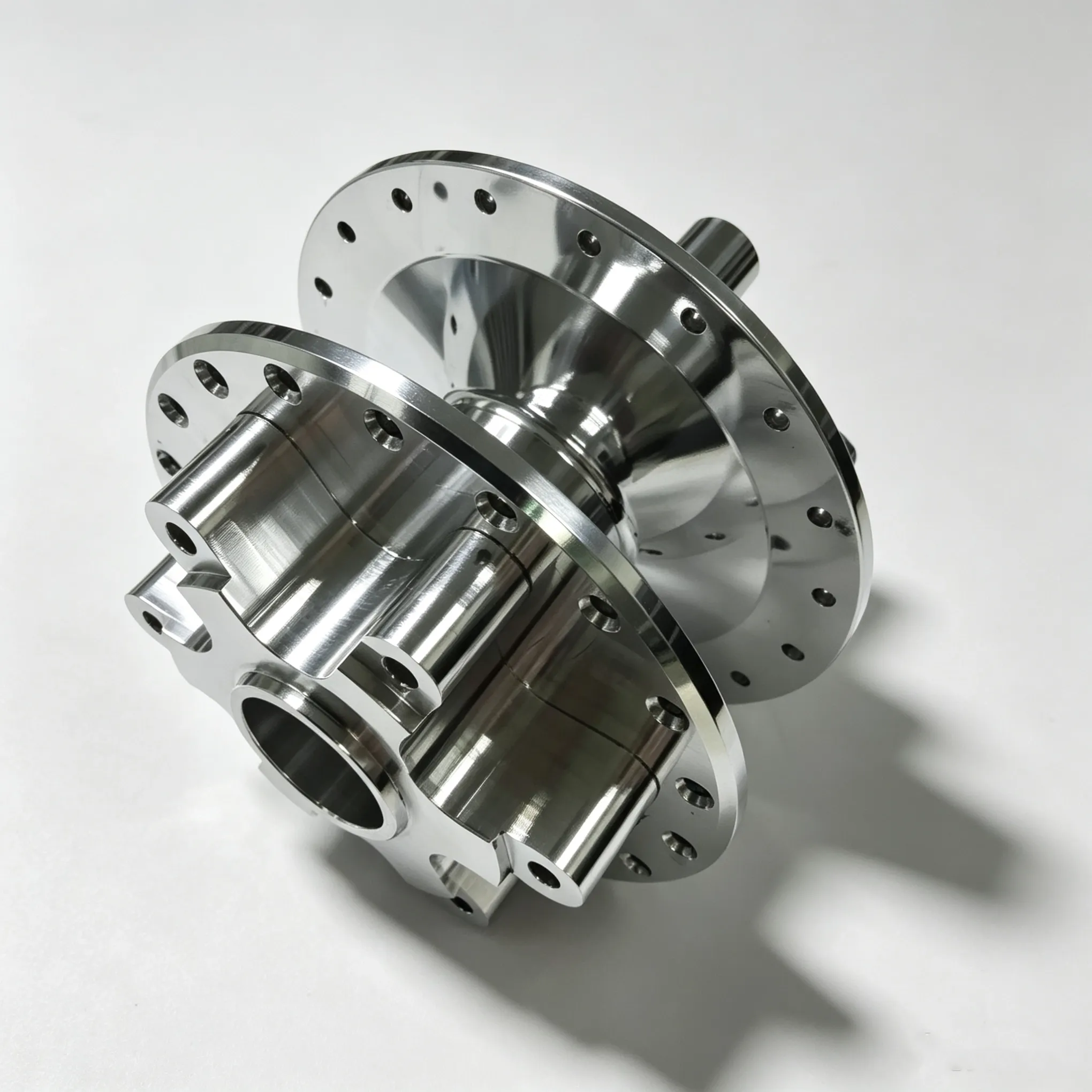
Arm links, joint brackets and structural adapters answer to the same constraint: keep the far end from deflecting without adding mass, because every gram there is paid for again at every joint that lifts it. Section geometry does most of that work — tube depth, ribs, interface bosses — while the alloy sets the strength margin. This is where the aluminum decision lives.
End effectors, grippers and tooling
Gripper bodies, fingers, tool plates and sensor mounts mix requirements: rigidity under grip and contact forces, wear surfaces where parts slide or clamp, sometimes electrical isolation. Metal and plastic usually coexist here — an aluminum body carrying nylon or POM pads and insulators at the contacts.
Housings and motor mounts
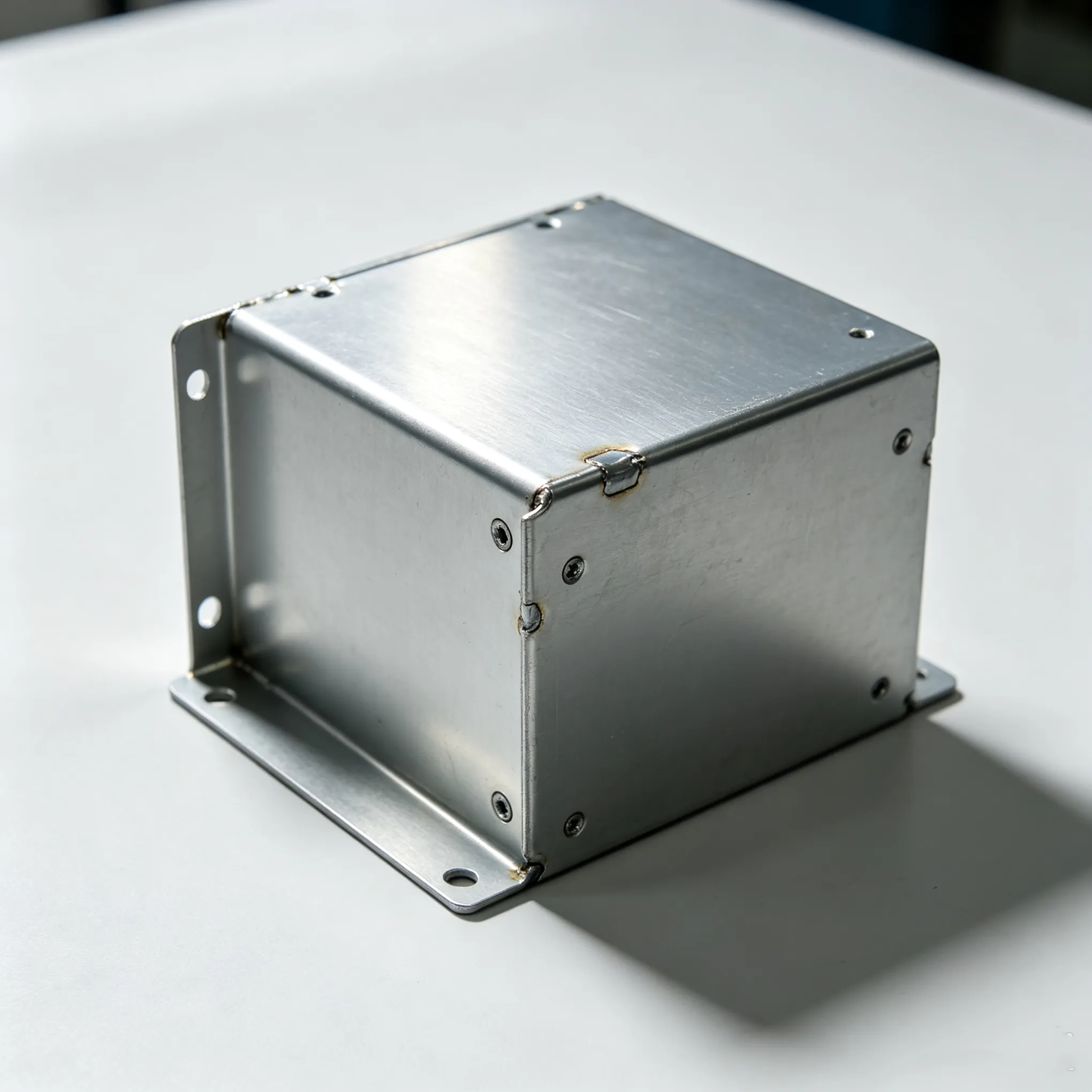
Housings, enclosures and motor mounts answer to bolt clamping, vibration and alignment — and above all to their environment: coolant mist, washdown, dust, humidity. That exposure is where the finish decision concentrates, and where mounting-face control matters more than exotic alloys.
Material by component
6061 and 7075 on the structure
For robot structure, the confirmed aluminum pair splits cleanly by job: 6061 carries the general structure — brackets, plates, mounts — and 7075 takes the arm-link class, where a higher strength margin at low weight is the point. Which one a specific link needs depends on its load path and interfaces — so compare the two workhorse aluminum alloys for robot structures before locking the drawing.
Nylon and POM for wear and insulation
Where a part slides against metal, must not gall a mating surface, or must isolate a sensor from the structure, a machined plastic usually does the job better. Nylon brings toughness and wear life; POM brings rigidity, low friction and steadier dimensions — nylon may drift with humidity, so check the moisture your cell sees.
Stainless where the environment attacks
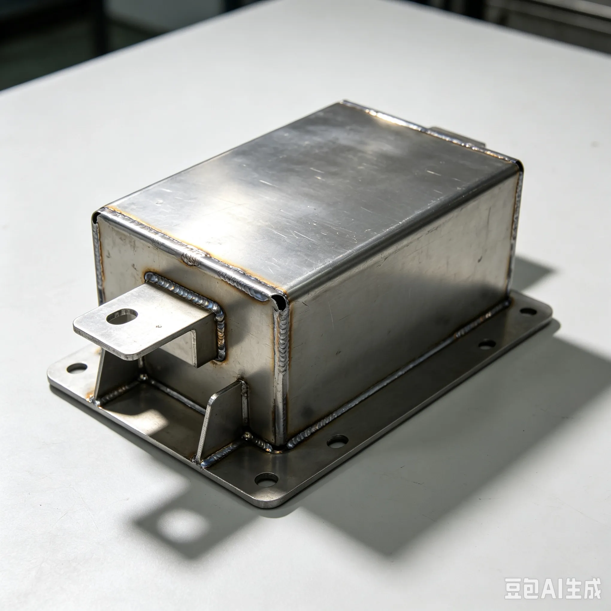
Parts that see washdown, coolant mist or humid air deserve stainless there — 303, 304, 316 and 17-4 are all on the confirmed list, and grade selection is its own comparison. A common pattern is hybrid: aluminum for the bulk, stainless only at exposed sliding or corroding points, so the weight penalty stays local.
Tolerance by function
Tight bands belong where parts meet parts — bearing seats, joint bores, dowel-located interfaces and the mounting faces that set alignment — and non-critical faces can stay at the standard working tolerance. ProLathe machines to ±0.05 mm as a standard working tolerance — treat it as the default here, and keep the tight-band list short: every added band is one the shop must hold in cutting and prove in inspection.
Finish by environment
Finish follows the cell, not the catalog — mapping the confirmed in-house list to part classes:
Anodizing on aluminum structure and end-effectors — the usual default for corrosion resistance and a harder surface.
Passivation on stainless parts that see washdown or chemicals — it supports the corrosion resistance the grade was chosen for.
QPQ on steel parts where wear and corrosion bite together — sliding steel components in dirty or damp cells.
Painting on housings and covers that need a specific color or an added environmental barrier.
Sandblasting where a uniform matte texture is wanted — usually as preparation before anodizing or painting.
The same bracket may deserve different finishes in a dry lab cell and a washdown cell.
Run the per-part checklist
Fill one line per part, sorted by class, before requesting quotes:
Part class → structural link / end effector or tooling / housing or motor mount: ______
Material → alloy or plastic, and the reason (load path, environment, insulation): ______
Aluminum call → 6061 or 7075 decided for structural parts: yes / no
Plastic call → nylon or POM decided for wear and insulation parts: yes / no
Corrosion call → stainless or a protective finish at exposed points: yes / no
Tight bands → listed only on bearing seats, joint bores and interfaces: ______
Default faces → left at the standard working tolerance: yes / no
Finish → matched to the cell environment: ______
The checklist records and organizes decisions; it does not validate them — loads, deflection and service life only become evidence when your own assembly is tested. It keeps every specification decision explicit and per part — what a shop needs to quote accurately and a review needs to challenge quickly.
For reference, ProLathe's confirmed capabilities:
CNC turning and milling to ±0.05 mm
Materials: aluminum 6061/7075, stainless 303/304/316/17-4, steel, brass, bronze, nylon and POM
In-house surface finishing: anodizing, QPQ, sandblasting, passivation, painting
Quotations within 24 hours
ISO 9001 certified
Robot parts rarely stop at one revision: the first machined set teaches you what the assembly does, and the second is where these choices lock in. Simple parts in small batches run in about 7 days, while complex or high-volume work is quoted separately — plan the loop before the design freezes.
Run the per-part checklist on your current robot build and record a material, tolerance and finish line for every part before requesting quotes.
Two follow-ups depending on where your check lands:
Recording those lines is the whole action this page asks of you.